Mounting the Dome on the Bearing
I have seen a lot of information on the dome and what bearing to buy, but very little about how to actually mount the dome to the dome ring, and then mount that on the bearing. Rockler and Lee Valley Bearings are the bearing of choice for rotating your droid's head. They can be found here:
LEE VALLEY TOOLS
http://www.leevalley.com/hardware/page.aspx?c=2&cat=3,44013&p=44014
You want Bearing# C - 17-3/8" Lazy Susan Bearing
ROCKLER WOODWORKING AND HARDWARE
http://www.rockler.com/
You want Bearing# 12451 - 17" Lazy Susan Swivel Heavy Duty
Do a SEARCH (on the left side) for 12451 and the page will come up.
Now, on to the mounting. I started by locating the rubber mounts on the bearing. The portion we are working with for mounting the dome is the INNER RACE RING of the bearing. Locate the rubber mounting feet and pull every other one out - (should be 6 of the 12 rubber feet). This will reveal a partially drilled through hole under the rubber foot. Size the hole to a drill bit and carefully drill all the way straight through the bearing.
There were 12 rubber feet on mine, each spaced at 30 degree increments around the circle. Use these degree increments to locate and mark the lip of the dome ring at every 30 degree point. Then remove every other so you only have 6 remaining. Next, measure from the center of one hole to the center of the hole exactly opposite and across the bearing from it. This will give you the diameter of the circle you will need to make on the dome ring to indicate where to drill your holes.
Cut a cardboard circle out to these measurements and lay it CENTERED on the dome lip. Check the spacing on all sides of the cardboard and make sure it is perfectly centered. Carefeully mark each drill point on the degree markers. Now that the drill points are clearly marked, select a drill but that matches the diameter of the flathead bolts you have selected for the job. Drill the holes.
This sounds like a lot of measuring and degree-checking, but it will save you a LOT of grief so that the holes will all lilne up. I did not do this and ended up having to re-drill a second set of holes to make mine line up . . . it is worth the extra prep time.
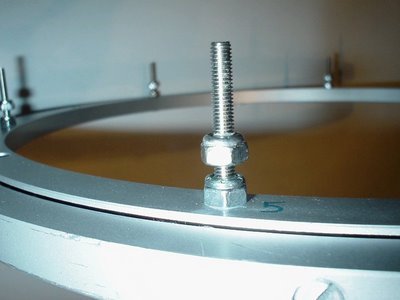
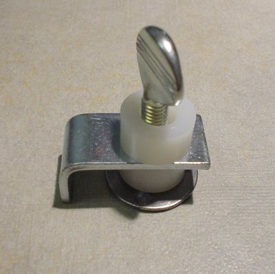
You will need bolts and lock nuts to create the Dome-Ring mounting posts. These are what the dome ring will rest on. Feed the bolts through from the bottom of the bearing and tighten one lock nut ALL the way to the bearing, holding the bolt firmly in place. Do this for all 6 alternating holes. When you have finished that, put a SECOND lock nut on each bolt and tighten it ALMOST all the way down. these nuts will serve as the adjustable point on which the dome ring will sit. The idea is that if you have the bearing sitting on a table top or workbench, that you can adjust them all so that the dome ring will rotate evenly, and just BARELY clearing the surface of your table or bench.
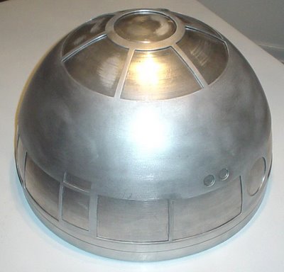
This is what mine ended up looking like when done:
LEE VALLEY TOOLS
http://www.leevalley.com/hardware/page.aspx?c=2&cat=3,44013&p=44014
You want Bearing# C - 17-3/8" Lazy Susan Bearing
ROCKLER WOODWORKING AND HARDWARE
http://www.rockler.com/
You want Bearing# 12451 - 17" Lazy Susan Swivel Heavy Duty
Do a SEARCH (on the left side) for 12451 and the page will come up.
Now, on to the mounting. I started by locating the rubber mounts on the bearing. The portion we are working with for mounting the dome is the INNER RACE RING of the bearing. Locate the rubber mounting feet and pull every other one out - (should be 6 of the 12 rubber feet). This will reveal a partially drilled through hole under the rubber foot. Size the hole to a drill bit and carefully drill all the way straight through the bearing.
There were 12 rubber feet on mine, each spaced at 30 degree increments around the circle. Use these degree increments to locate and mark the lip of the dome ring at every 30 degree point. Then remove every other so you only have 6 remaining. Next, measure from the center of one hole to the center of the hole exactly opposite and across the bearing from it. This will give you the diameter of the circle you will need to make on the dome ring to indicate where to drill your holes.
Cut a cardboard circle out to these measurements and lay it CENTERED on the dome lip. Check the spacing on all sides of the cardboard and make sure it is perfectly centered. Carefeully mark each drill point on the degree markers. Now that the drill points are clearly marked, select a drill but that matches the diameter of the flathead bolts you have selected for the job. Drill the holes.
This sounds like a lot of measuring and degree-checking, but it will save you a LOT of grief so that the holes will all lilne up. I did not do this and ended up having to re-drill a second set of holes to make mine line up . . . it is worth the extra prep time.
You will need bolts and lock nuts to create the Dome-Ring mounting posts. These are what the dome ring will rest on. Feed the bolts through from the bottom of the bearing and tighten one lock nut ALL the way to the bearing, holding the bolt firmly in place. Do this for all 6 alternating holes. When you have finished that, put a SECOND lock nut on each bolt and tighten it ALMOST all the way down. these nuts will serve as the adjustable point on which the dome ring will sit. The idea is that if you have the bearing sitting on a table top or workbench, that you can adjust them all so that the dome ring will rotate evenly, and just BARELY clearing the surface of your table or bench.
This is what mine ended up looking like when done:

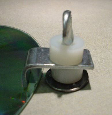
 When you think you have that about right, move the dome ring over the holes and slip it in place.

 Now swivel the dome ring around and check to make sure clearance is uniform all the way around the dome.
 I plan on cementing my dome to the dome ring and either allowing gravity to hold the head on or possibly installing a lock mechanism on top of 2 of the bolt posts (accessible through an opening dome panel).
posted by Shadow Walker at 9:24 AM
0 comments
![]()

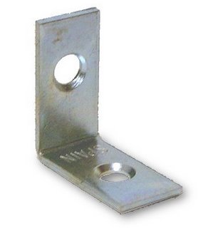
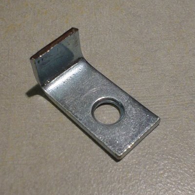
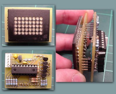
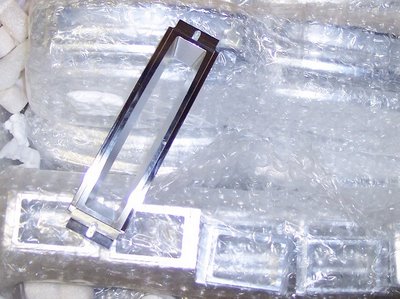
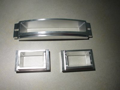
 Then I begin stacking them like this:
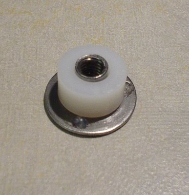
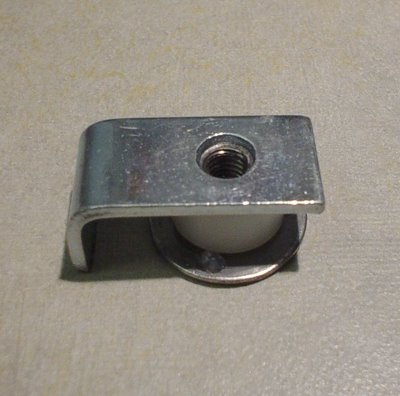

 These mounts could also be modified to mount the logic displays as well, and they make for fast, easy removal for servicing or upgrade of parts from resin to aluminum.